
Multi-terminal VSC HVDC Modeling |
|
|---|
The goal of this project is to develop a multi-terminal VSC HVDC model and to implement this model into large power systems to enable integration of renewable energy sources like off-shore wind. The model is written as a user-defined model in DSA Tools. The proposed 4-terminal VSC HVDC (4TDC) system topology is built in PSAT of DSA tools, as shown in Fig. 1, with the right side connected to two independent off-shore wind farms and the left side connected to interconnected AC grids.
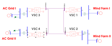
Fig.1 4TDC static model in PSAT
The dynamic model of a 4TDC system is written in TSAT User Defined Mode (UDM) editor, with both a graphic interface and ASCII code. The main functions in the controllers are: DQ transfer, Phase Locked Loop (PLL), control functions such DC voltage control, active power control and reactive power control, modulation index and phase angle calculation. The normal control mode for a 4TDC system is one station controlling DC voltage while the others control active power. A simplified control structure of each converter is shown in Figure 2.
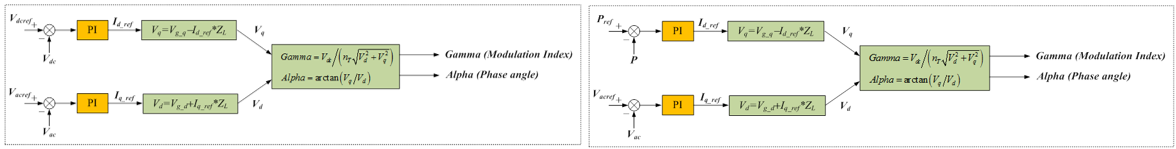
Fig.2 Simplified control structure for different converters
Based on the proposed topology, a dynamic simulation is performed and a generation trip at terminal 3 is tested. The results show that the 4TDC system controlled both the DC voltage and the active power during the disturbance, and it can also provide reactive power to hold bus voltage.
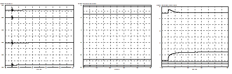
| (a) DC voltage | (b) Active power injection to AC grid | (c)Reactive power injection to AC grid |
Fig.3 Dynamic interactions of converters after a 10% generation trip of one AC grid terminal