
GIC Impact for Transformer Harmonics and Reactive Power |
|
|---|
By perturbing Earths magnetic ?eld, geomagnetic disturbances (GMDs) can induce quasi-dc earth surface potential (ESP). ESP gives rise to low-frequency (0.1mHz0.1Hz) geomagnetically induced currents (GICs) that ?ow in the loops of transmission lines, power transformer windings with grounded neutrals, and the grounding grid of substations [1]. During GMDs, GICs in power systems cause half-cycle saturation of transformers, then produce harmonics and increase reactive power consumption and transformer overheating issue, which can lead to transformer damage, voltage dips, relay misoperation, overload of reactive power compensating capacitor and system stability problems [2].
In order to simulate the harmonics and reactive power during GMDs, magnetic circuit method (MCM) is selected as the simulation method for its accuracy and efficiency. Actually, MCM has been implemented in the electromagnetic transients program (EMTP) software for over 15 years, such as the unified magnetic equivalent circuit (UMEC) in PSCAD, the BCTRAN model in ATP. But to some extent, the existing commercial EMTP software are hardly uses to calculate the harmonics and reactive power during GMDs as the MCM in EMTP software mainly focus on the positive sequence magnetic flux, failing to represent the impact of GICs which generate zero sequence flux.
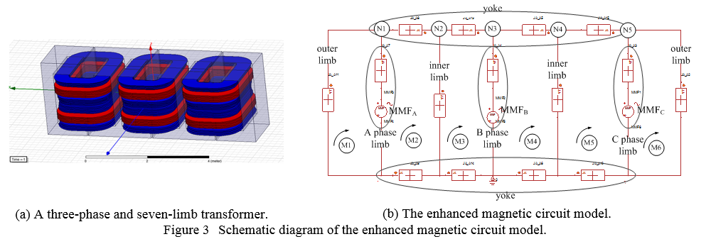
To get rid of the limitation of existing magnetic circuit model, we uses an enhanced magnetic circuit method (EMCM) to calculate the harmonics and reactive power during GMDs. Similar to the models in reference [2], EMCM is carried out by the following steps:
Step1. Use the geometry of transformer to create the magnetic resistance network considering the nonlinearity of B-H curve or hysteresis loop.
Step2. Determine the ac component of flux by the operating condition, also initialize the dc flux component.
Step3. Iterate the dc component of flux to obtain three-phase identical GICs.
Step4. Calculate the magnetic motive force (MMF) and get the waveform of magnetizing current.
Step5. Use matrix pencil method (MPM) to calculate the harmonics and get the reactive power consumption.
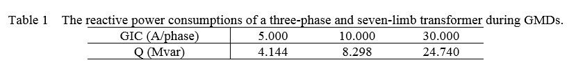
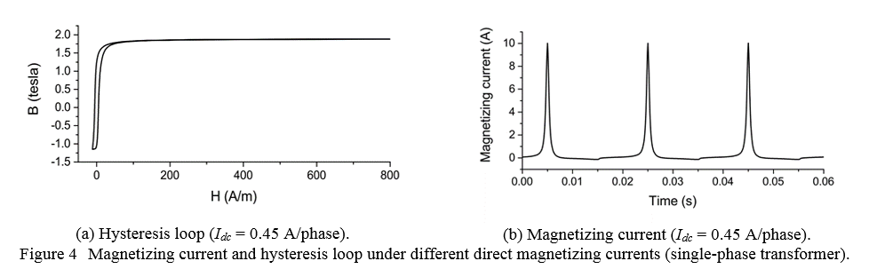
Like example of a three-phase and seven-limb transformer in Figure 1(a), the EMCM model is shown in Figure 1(b) and the reactive power consumption can be seen in Table 1. Figure 2(a) shows the hysteresis loop of a single-phase transformer under 0.45A/phase GIC while the magnetizing current can be found in Figure 2(b).
References
[1] Zhuohong PAN and Yilu Liu, Harmonics current and reactive power consumption of three-phase seven-limb transformer during geomagnetically disturbance, technical report, 2014.
[2] X. Li, X. Wen, P. Markham, and Y. Liu, Analysis of nonlinear characteristics for a three-phase, five-limb transformer under dc bias, IEEE Transactions on Power Delivery, vol. 25, no. 4, pp. 25042510, Oct 2010.